Phil-duino
A collection of Arduino tutorials put together to help a colleague dive into embedded systems!
Digital IO
Phil, are you ready to add another tool to your embedded systems Swiss Army knife? The next step on our journey to total world domination building and programming a line following robot is to learn about digital inputs and outputs.
GPIO
You may have seen the acronym GPIO floating around. EE majors love acronyms, hence why we refer to Electronic Engineering as EE. It also give us a sense of intellectual superiority as the next question that follows is naturally, “what does insert_acronym_here mean.” But really, all we are doing is impeding scientific communication by inflating our own egos.
GPIO stands for General Purpose Input and Outputs. We have already seen an example of using digital outputs when we controlled the built-in LED in Tutorial 1. The Arduino Nano has plenty of GPIO for us to play with.
So, lets take a look at controlling some external components!
Digital Outputs
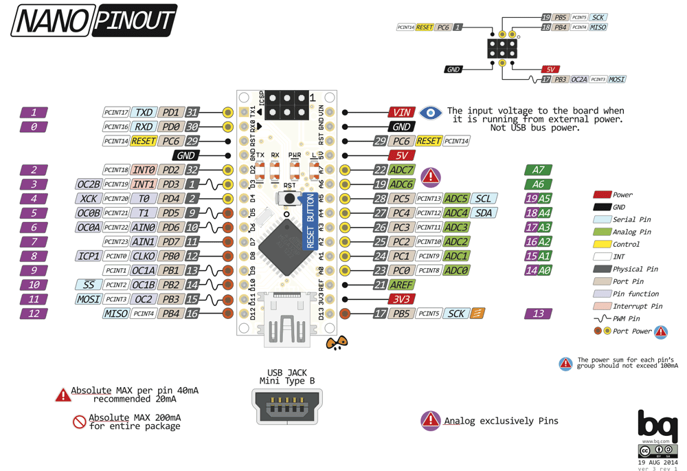
Which pins do you think can be configured as digital outputs? The ones marked with a “D”, of course. Also, some of the ones marked with an “A” aswell! What a time to be alive.
For a full list, see the image below. Hint, look for a purple number. That purple number will become important very soon.

Connecting some LEDs to the Arduino Nano
To flash some external LEDs, we need to connect them to the Arduino Nano. To do this we need:
- An Arduino Nano
- 4 x 220 Ohm resistors
- 4 x LEDs
- A solderless breadboard
- Some hookup wire
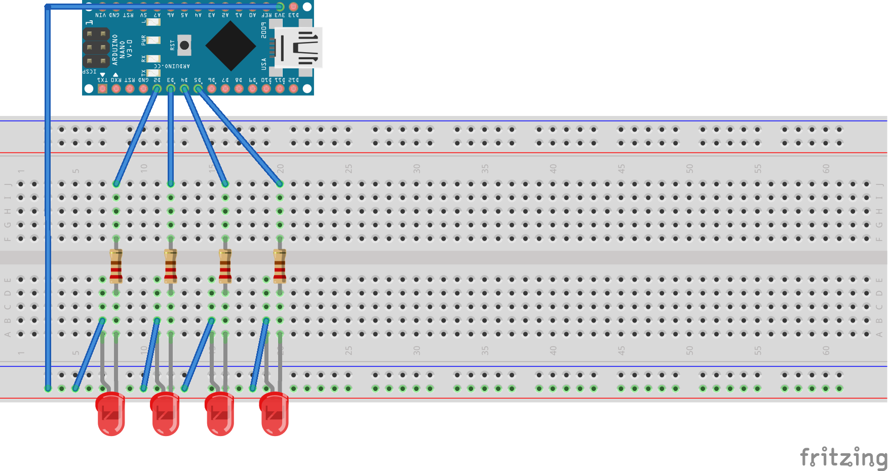
Hook everything up as shown in the image below.

Things to pay attention to:
- The resistor is there to limit the current to the LED.
- The longer leg is the positive leg, also known as the anode in electronics, or the cathode in chemistry. The current convention for electronics is different to the current convention for chemistry. Why? Because fuck you, that’s why.
- +3V3 goes to the voltage rail on the breadboard.
And that’s it for the hardware! Now, onto the code!
Code
Once again, we start with our good friend main.cpp.
#include <Arduino.h>

void setup() {
    // put your setup code here, to run once:
}

void loop() {
    // put your main code here, to run repeatedly:
}
And that is as much as I am going to help you this time, Phil. Use Tutorial 1 as a guide to complete the digital output homework exercises. I will post the answers after Phil has attempted them.
Digital Output Homework Exercises
- Flash all the LEDs at a frequency of 2 Hz
- Flash the LEDs individually, left to right then right to left, at 4 Hz
- Count up and display the number in binary on the LEDs at a frequency of 3 Hz
Digital Inputs
Now that we have digital outputs under control, it is time to start reading some digital inputs.
Add some push buttons to the breadboard, as shown below. You will need:
- 2 x push buttons
- 2 x 10k Ohm resistors

Those resistors are pull-up resistors. They are there to pull-up (surprise surprise) the voltage on the pin. When the switch is open, the pin will be pulled-up to +3V3, when the switch is closed the pin will go to ground.
That’s enough hardware for today, time to get back into the code!
Code
Oh main.cpp, we have to stop meeting like this.
#include <Arduino.h>

void setup() {
    // put your setup code here, to run once:
}

void loop() {
    // put your main code here, to run repeatedly:
}
Reading digital inputs is pretty much the same as writing to outputs. Instead of setting the pins up as outputs, set them up as inputs!
Instead of writing HIGH or LOW to the pin, read if they are HIGH or LOW!
So, lets define a pin to read from and use pinMode() to set it up as an input.
#include <Arduino.h>

#define PUSH_BUTTON 11

void setup() {
    pinMode(PUSH_BUTTON, INPUT);
}

...

}
Oh shit yeah! Look at you go Phil, you big code monkey!
Now, lets print the state of the push button to the Serial Monitor. Take a guess what the name of the function that reads digital inputs is called..?
...

void loop() {
    Serial.print(digitalRead(PUSHBUTTON));
    delay(1000);
}
Did I just call a function from within another function?! Can you even do that?! YES!
Digital Input Homework Exercises
- Display the state of the push button on the LEDs
- Use both push buttons to cycle through the LEDs. SW1 moves the LED left, SW2 moves the LED right. Only one LED should be on at a time.
- Use both pushbuttons to change the binary number shown on the LEDs. SW1 increments the number, SW2 decrements the number.
NOTE! Work in progress!