Phil-duino
A collection of Arduino tutorials put together to help a colleague dive into embedded systems!
Analog IO
Time for hard-core anal-og, Phil. Bite the pillow, I’m going in dry…
Analog vs Digital
Analog is continuous, digital is discrete. For example, say we have a voltage range of 0 to 5 V. An analog representation would include all the values between 0 to 5 V. In theory, that is an infinite amount of values! A digital representation would have to quantize that range into discrete steps. If we had 1-bit to work with, we could assign the binary value 0 to anything between 0 and 2.5 V, and binary value 1 to anything between 2.5 and 5 V. This is a bit of an over simplification, but you have to know your target audience. And my target audience is simple indeed.
So, lets get down to business. And, just like Captain Li Shang training Mulan to defeat the Huns, I’ll make a man out of you.
Analog Read
Remember way back in tutorial 3 when we read from a digital pin? Well, guess what?! We can read from analog pins aswell!

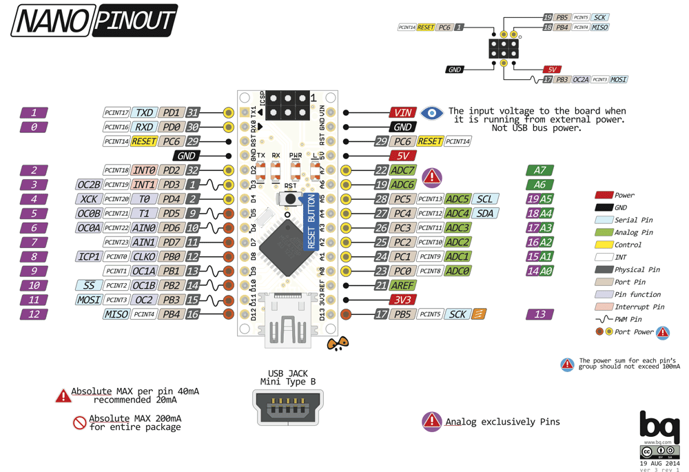
Can you figure out which pins from the image above are capable of analog reads? The ones with an ‘A’ next to them, of course! If you are wondering why only certain pins can be used for analog-y reading goodness, that is because lurking beneath the surface, embedded in the silicon of the microcontroller is an Analog to Digital Converter, commonly referred to as an ADC. Remembering that the Arduino Nano is just a wrapper around an ATmega328, this means that the analog pins on the Nano are connected to the 8-channel multiplexer connected to the 10-bit successive approximation ADC on the chip. What a mouthful!
Analog To Digital Converters
They convert analog signals to digital signals. How do they do it? Remember, we are making music, not pianos. But put simply, a dedicated little circuit outputs a little voltage, compares the output voltage to the input voltage and sets each bit in the ADC accordingly.
So, how does our 0 to 5 V get quantized? It gets chopped up by the number of bits in our ADC! In our case, we have 10-bits.
2^10 = 1024, so we can divide our 0 to 5 V range into 1024 little chunks.
5V/1024 = 0.0048828125 V = 4.88 mV! That is a pretty nice resolution for a little chip worth $3.47 on Element 14!
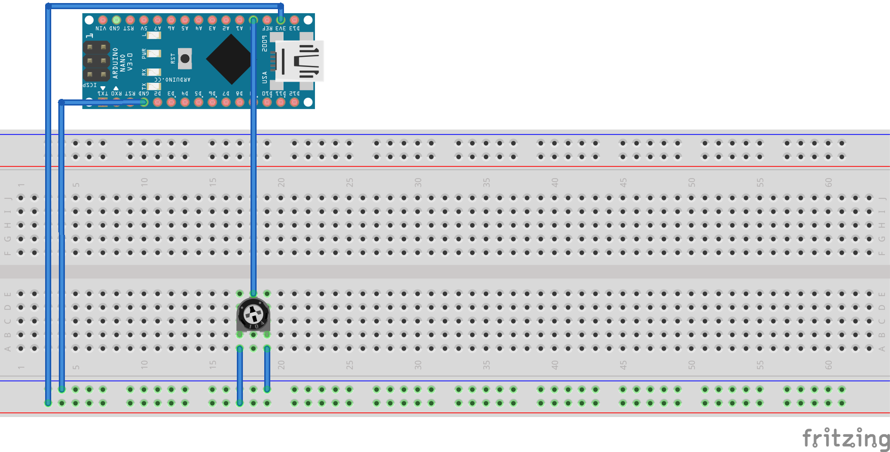
Connect a potentiometer to the Nano
You will need:
- A 10 k Ohm potentiometer
- Some hookup wire

A potentiometer is a variable resistor. Turn it one way to increase resistance, turn it the opposite way to decrease resistance. If you put 5V in one end, and 0V in the other end, you have a voltage divider. The middle pin will give you the divided voltage. Input that voltage into AO of the Nano and we are ready to code!
Code
Ahh main.cpp, we must stop meeting like this. People are beginning to talk…
#include <Arduino.h>

void setup() {
    // put your setup code here, to run once:
}

void loop() {
    // put your main code here, to run repeatedly:
}
The steps we need to follow should be becoming pretty familiar by now:
- Define a pin
- Set it as an input
- Use a standard library function to interface with the peripheral
#include <Arduino.h>

#define ANALOG_PIN 0

void setup() {
    pinMode(ANALOG_PIN, INPUT);
    Serial.begin(115200);
}

void loop() {
    Serial.println(analogRead(ANALOG_PIN));
    delay(250);
}
Open the Serial Monitor, turn the potentiometer and bask in your own magnificence!
Analog Write
Let me fill you in on a dirty little secret of the Arduino Nano, it doesn’t have a built-in Digital to Analog Converter, or DAC. So, the name ‘Analog Write’ is a bit of a stretch. What it really should be called is ‘Pulse Width Modulation Write’, or ‘PWM Write’. But if you feed the PWM signal into a low pass filter, BAM! You have a DAC.
But anyway, for alot of things, just using PWM is a decent enough trick to get ‘analog’ outputs.
What is Pulse Width Modulation?
PWM is the name we give to varying the ratio of on-time to off-time for a square wave, where the on-time is the pulse width. It is best explained with an image, which the kind folk at Arduino have provided.

If the square wave is high 0%, we get 0V, no surprises there.
Now, if the square wave is high 25%, it is ‘perceived’ as if we have 1.25 V. 50%, 2.5 V. And so on. By modulating the pulse width, we can fake any DC voltage from 0 to 5 V.
Analog Write
I think you can figure out which function we need to use. If you can’t, just close the browser and do something a little more suited to your mental aptitude, like finger painting.

Can you figure out which pins from the image above are capable of analog writes? The ones with a little sine wave next to them!
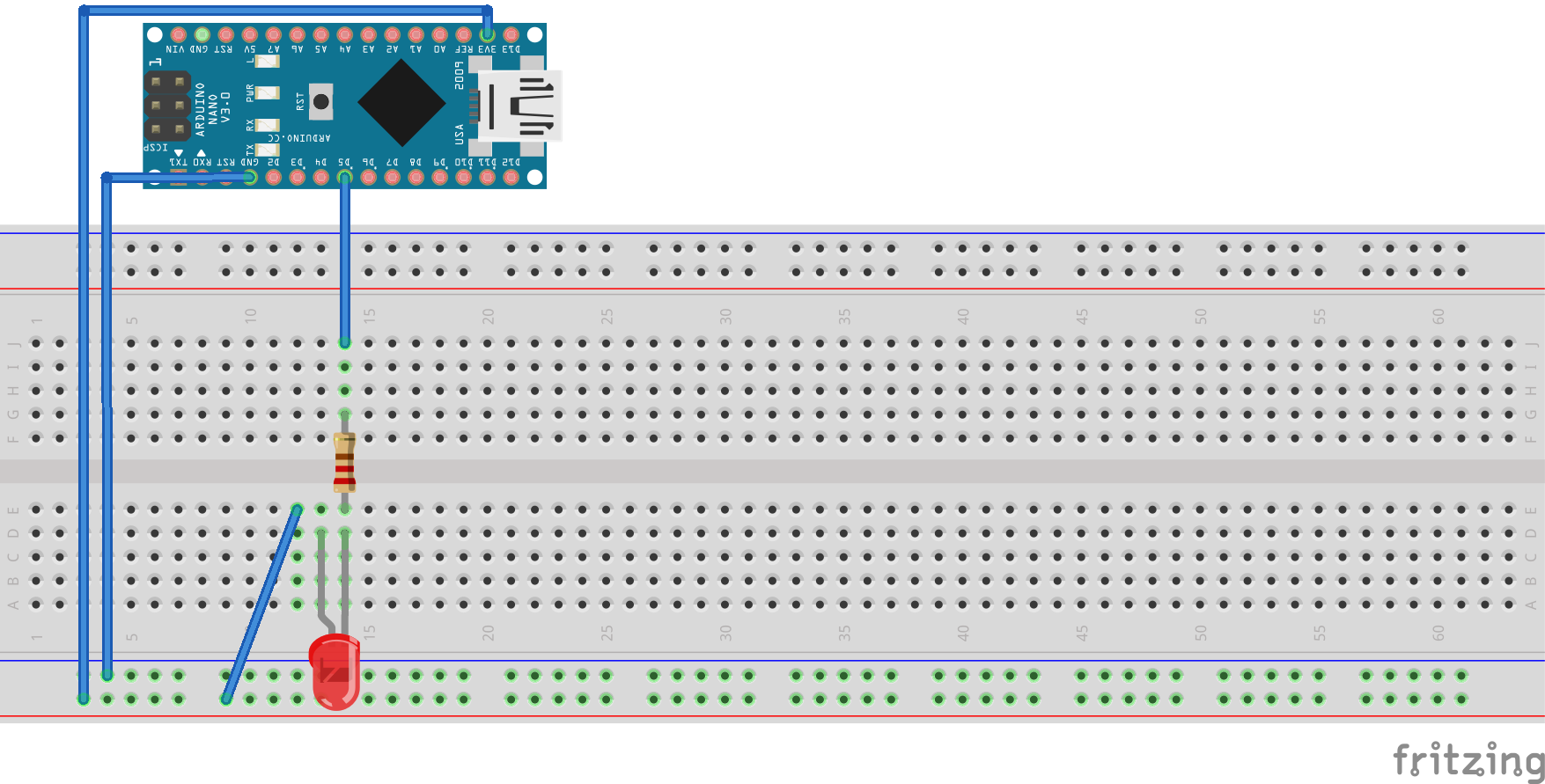
PWM an LED
You will need:
- A 330 Ohm resistor
- An LED
- Some hookup wire

Code
Back to main.cpp!
#include <Arduino.h>

void setup() {
    // put your setup code here, to run once:
}

void loop() {
    // put your main code here, to run repeatedly:
}
Those familiar steps again:
- Define a pin
- Set it as an output
- Use a standard library function to interface with the peripheral
#include <Arduino.h>

#define PWM_PIN 5

void setup() {
    pinMode(PWM_PIN, OUTPUT);
}

void loop() {
    analogWrite(PWM_PIN, 127);
}
Damn, Phil. You are getting good!
Homework Exercises
- Use the potentiometer to set the brightness of the LED
- Connect 4 LEDs to the Nano and use them as a simple voltmeter for the potentiometer. Each LED should represent a range of 1.25 V. All LEDs should be off when the pot is full counter clockwise. As the pot is rotated, each LED should come on sequentially. For example, 0 V -> 0000, 1.25 V -> 1000, 2.5 V -> 1100, 3.75 V -> 1110 and 5V -> 1111
- Fade a LED from full on to full off at 1 Hz
- When you fade the LED it seems to be logarithmic. Make it linear.